TECHNICAL SPECIFICATION
1.0 Introduction
The ‘FLOWPLUS’ series pump set and controller are the key components for a high quality submersible pump system. This system is pollution free and is an ideal solution for remote homes, wildlife and stock watering problems without violating the environment and it’s almost free of cost just
you install the system and forget it.
‘FLOWPLUS’ SOLAR pumps are positive displacement, low voltage, DC powered, submersibles constructed of high quality stainless steel. These pumps are designed for corrosion resistance quality.
The controllers are solid-state DC power converters designed as the interface between ‘FLOWPLUS’ series pump set and a DC power source. The purpose of the controller is to maximize the total daily water output while providing protection for the pump and the DC power source.
These FLOWPLUS series pump systems are easy to install, please read this manual or observe the CD to become familiar with the pump and controller features, functions, connection points and various configurations. For future reference, keep this manual and other relevant product information in a safe place.
Precautions
Safety First – Always understand what you are doing when working with any form of electric system. To avoid any damage or personal injury, work only when you are sure.
Shutdown the power supply of the system while working
Do not attempt to feed live wires into the controller or product damage and/or personal injury may result.
Do not exceed the power rating of the controller. Mount the controller in a shaded, well vented and vertical position and lock and key.
Warnings
All ‘FLOWPLUS’ SOLAR controllers have a maximum voltage rating. Exceeding these ratings will destroy the controller and void the warranty.
Do not touch controller input or pump wires together to test current.
2.0 Product Overview
The FLOWPLUS series pumps and controllers are designed to operate with variety of DC power sources. The most common of these are SOLAR electric modules and. When properly installed and configured, the unique features incorporated into this stand-alone system will automatically control and protect your pump system permitting several years of dependable, trouble free service.
Buyer is advised to install the systems such as overload protection, voltage variation protection, dry run protection this will result in almost zero maintenance condition.
2.1 Controller Features
Current boosting for matching the load requirements of the pump
Voltage regulation of the SOLAR electric array at its maximum power point
Over-current protection via integrated electronic circuit breaker, with manual or automatic reset features
Reverse polarity protection (10 amperes maximum) on the input terminals
Voltage and current limiting to pump motor
Transient protection and surge suppression
Adjustable pump motor voltage control for precision output flow
Adjustable input voltage for system optimization or SOLAR modules
System ON/OFF switch
Weather resistant cast aluminum enclosure with hinged door
Rising clamp screw terminal blocks – no fork terminals required
User selectable pre-adjusted input voltage configuration and power source selection
2.2 Application
The application of controllers are designed for the interface between the FLOWPLUS series pumps and the DC power sources as well as peripheral pump system signal devices. The controllers are capable of operating with DC inputs, SOLAR electric modules.
3.0 Installation and Operation
The following sections are outlined in a step by step format to guide you through the installation, configuration and system power-up of the FLOWPLUS pumps and the controllers. Before installing the pump system read all product manuals and reviews all system components to become familiar with the physical and electrical layout. Check all equipment for any product damage. Refer to applicable figure(s) as a guide during the installation. Controller door must be closed during normal operation.
3.1 Location
As the majority of system installations vary greatly, only general comments can be made as to location. Prior to installing the system, it is suggested to make a system layout plan. During the system layout, take into consideration any potential shading of the SOLAR electric modules, wire runs, wire size, conduit runs, trenching, controller accessibility, tank location, pump head and etc. There is no substitute for a good plan!
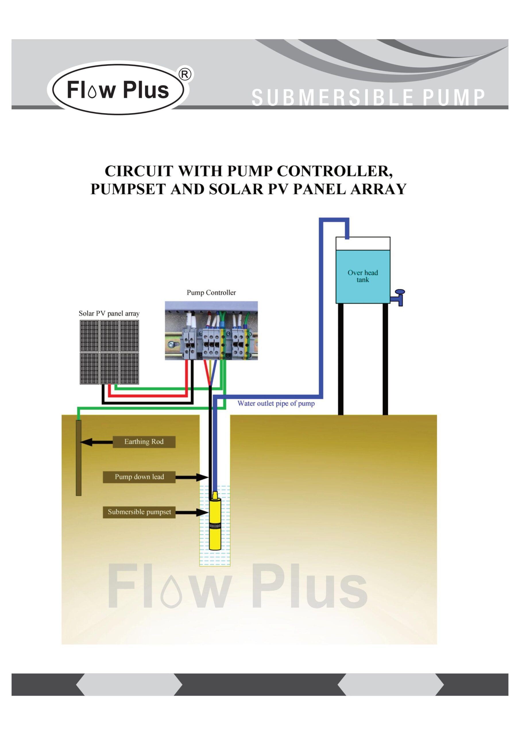
The controllers can either be mounted indoors or outdoors but in protected area only Locate all system equipment as close as possible to each other. Generally the controller is mounted on the north side of a pole which has SOLAR electric modules mounted on top of it. The panels should be located close to the well (bore hole). This general physical layout is conducive to clean installation aesthetically and electrically. For better performance install solar panels facing SOUTH direction after observing sun
direction.
3.2 System Design Basics (Read carefully before installation)
• For optimum pump performance make sure that the wire is sized properly for the length of run between the pump and the SOLAR modules. Wire sized too small will cause a decreased output from the pump. Keep the distance from the SOLAR modules to the pump as short as possible.
• Make sure the discharge pipe is sized proper for the length of run. Friction loss in a pipeline over a long distance will result in head loss and this will pump and thus reduce the flow rate also. Consult your FLOWPLUS Pumps distributor if there is any question.
• Never rest the pump on the bottom of the well (bore hole). This can cause the pump to fill with mud and damage the diaphragm. Suspend the pump five feet (1.5 meters) or more above the bottom of the well (bore hole).
• Due to the aggressive action of DC power, it is essential the wire splice at the pump be made correctly. This splice must be watertight. Improper sealing of the splice will cause poor pump performance and may cause damage to the system.
• Never install the pump over 50 feet (15 meters) under the static water level. Excessive water pressure on the pump housing may cause seal damage and allow water to enter the motor housing.
• Never chlorinate a well while the pump is installed. Heavy concentrations of chlorine will damage the diaphragm and seals.
• Never install the pump in a well that has or has had an oil-lubricated line shaft turbine in it. Any drip oil remaining in the water may damage the diaphragm and seals.
• If the pump is used in a well over 100 feet (30 meters) deep, install a check valve a b o v e t h e pump. This will help relieve some of the pressure on the internal check valves and will keep any sediment from entering back into the pump.
If you have not purchased a complete system from your supplier the following formulae will be useful:
Selecting the components for the pumping system
SOLAR PV panel (SOLAR photovoltaic panel) selection
Use the following formula to select the correct SOLAR PV panel(s):
Power of pump (watts) x 1.3 ~ 1.6 = power rating of SOLAR PV panel(s) in watts
For example:
A 300 watt pump needs a minimum of 390 watts of PV panels to drive it:
300 watt pump x 1.3 = 390 watt PV panel
You may need combinations of panels, especially for the larger pumps.
When you have panels in parallel, add the current of the panels and the wattage.
Note: If connecting in parallel you will need Schottky Diodes in series with each panel.
When using panels in series add the voltage and the wattage. For example:
2 x 12 volt 100 watt panels in parallel become a 12 volt 200 watt system
2 x 12 volt 100 watt panels in series become a 24 volt 200 watt system
Note: Your pump supplier will be able to help you with panel selection
The controller will already be matched to the pump by your supplier.
SOLAR array installation
Sizing the SOLAR array
Be sure that PV array has been properly sized to meet the pump’s requirement. A PV array will produce its rated power when properly aligned with the sun and no dust or debris accumulation SOLAR panels offer peak performance in cooler temperatures. An undersized array can cause poor starting and reduced flow in low light conditions. An oversized array is recommended (at least +20%); the pump will start earlier and run for a long duration, as well as will result in higher performance in cloudy or hazy days.
SOLAR orientation
For optimum performance, the SOLAR array must be oriented with ±5˚ of true (SOLAR) south.
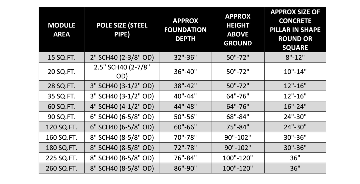
MOUNTING POLE GUIDES FOR TOP OF POLE MOUNTS
The following table provides guidelines for an average installation. Soil type varies widely from one region to another. The actual depth and diameter of the hole and the amount of concrete used is very dependent on soil type. Installations in loose, sandy soil will require a larger, deeper hole with more concrete than an installation in hard, rocky soil. The height of the above ground section of the pole and the wind speeds in the area also play an important role in determining the depth and diameter of the hole.
If in doubt, it is recommended that a civil engineer familiar with the area and local soil conditions is consulted.
* If a taller pole is needed for snow clearance or to clear nearby obstructions, the hole should be deeper to allow More of the pole to be placed in the ground. For each extra foot added above the ground, an increase of Approximately 6” (with concrete) will be needed in the ground.
General Procedure
When the hole is ready, place the pole inside until it is resting on the bottom of the hole. It is a good idea to fill the bottom 2 to 4 inches of the hole with rocks. Brace the pole plumb and pour concrete around it until it is filled up to ground level. Next, pour a little extra concrete on top, and using a trowel, start forming a mound around the pole so that the concrete slopes away from the pole. Allow the concrete to set up for at least 24 hours before installing the mounting rack.